• About
    • Battlebots
    • Sundry
  • Contact Me
Menu

Spencer's Hardware Blog

Street Address
City, State, Zip
Phone Number
An exploration into the process behind my designs.

Your Custom Text Here

Spencer's Hardware Blog

  • About
  • Projects
    • Battlebots
    • Sundry
  • Contact Me

Giant Audio Equalizer

May 19, 2018 Spencer Allen
Weller for scale

Weller for scale

My current place of employment makes a lot of large, dumb, orange LED boards. On occasion, old ones will come back from the field with bad pixels. Most of the time there is enough wrong with them that it would take too long to fix, and they get tossed.

Fortunately, I know where the trash bin is!

After filling my apartment with far more boards than I should have, I decided to finally do something with them.

What's wrong with them

Ninety-nine percent of the time the problems are constrained to the pixels. The LEDs are all through-hole, and automated through-hole assembly never works that well. Damaged dies and cold solder joints are common. Now stick the board in a enclosure outside for ten years, and you push these poor LEDs to their breaking point.

Fixing them up

To fix the boards, first I light them up. For the sake of professional responsibility, I wont explain that protocol here (sorry open-source hardware guys). But it's a digital protocol that my arduino can spit out.

I mark all of the pixels that are out, and shut off the board. Next, I go over the solder joints of all the offending LEDs with a soldering iron. Sometimes a cold solder joint finally gives up after a few years, and it's easily fixed by reflowing the joint.

Next I light it up again and remove the marks from any pixels that start working. The remaining pixels probably have a bad LED, so I shut it off again. The pixels are all quadruple-series strings, so a dead pixel could be caused by any one of four LEDs. I check each one with a multimeter in diode mode to find the culprit.

When I find a dead LED, I pull it out and replace it with a good LED from a sacrificial board.

Now the board should be fixed... for now. LEDs will continuously go out at random even still. They sometimes turn back on too; thermal expansion is weird. Every now and then I pull the boards down and go through the process again.

Now what?

I have several, large, bright, orange LED dot matrices that I can talk to with an arduino. So the obvious application is a giant audio spectrum analyzer. Similar projects been done a few times before, though often using a hardware fft such as the MSGEQ7. I decide to try a software implementation based around open music labs's Fourier library.

The design process

The open music labs library can run arbitrarily-sized FFT's (with proportionally massive RAM usage). It can also run the FFT's faster cousin, the Fast Hartley Transform (FHT). FHT's are faster because they only compute with real numbers. Real numbers are all I need, so I use the FHT library.

To read my desktop's audio stream, I first had to get windows to split my audio to my speakers and stereo output at the same time. This turned out to be, without exaggeration, the hardest part of this project. The solution deserves its own post, so I wont get into it here. 

After I got the audio stream coming out on a 2.5mm jack, I made what was likely my last ever radioshack purchase for a receptacle. I biased the signal up 2.5V using a capacitor coupled to a voltage divider, then fed it into my arduino's audio pin. I also fed in an old rotary pot for dimming control (did I mention these boards are bright?).

equalizer_board.JPG

For the analog sampling, the classic AnalogRead() was not going to cut it. "Arduino" and "Digital Signal Processing" don't often go together, so I had to splice in some bare-metal programming. Even so, back-of-the-napkin calculations showed my Nyquist was going to be in the range of 13kHz. That's pretty bad, even for audio, but I decided to try it anyways. I can try a faster processor later.

Code structure

The code follows a three-step process

Step 1: Sample the audio

I turn off interrupts, and run balls-to-the-wall analog sampling for 128 samples. This makes sure there is a consistent timing between each sample, which should hopefully improve my fidelity

Step 2: (every 10 iterations) read the brightness

I manually set the mux back to the pot, let is settle, and take a reading

Step 3: Send the data out

<Data transmission process redacted>

This process extracts every kHz of sample rate I can out of that poor Pro Mini, but it does mean I miss events that occur during the data shift process. Occasionally you notice a missed beat as a result. If only there were some kind of processor that could do both things in parallel...

Testing results

Having already worked with shifting data out to the sign, getting the FFT -> LED stream working was a breeze (the FHT library is pretty easy to use). Here's a 600Hz tone:

equilizer_tone.JPG

Ugh, talk about sideband leakage. My Nyquist is killing me here. Unfortunately there's nothing we can do about it now, so I test a few songs

Hmm, it's working, but It doesn't look quite right. After trying a few ideas, I realize that it needed a fade affect. I allow bins to rise in value instantaneously, but only allow them to decay slowly. Here's what is looks like now:

That's much better! Now I just have to add dimming and I can wra-

equilizer_noise.JPG

Adding dimming makes this show up, even with the sound off. At first I was annoyed, but then I realized it was one of the small things that make me love electronics. The dimming is achieved with a simple PWM signal. The default PWM frequency on Arduino is... 490Hz. And that line is right where I'd expect a 490Hz tone to go.

These panels all have synchronized dimming. So all of the LEDs turn on and off at the same time. Given that they are positively massive, it's no wonder this radiates enough energy for my audio cable to pick it up. I've dealt with interference at work, but this is definitely the first time I've seen an interference problem diagnose itself.

To "fix" the issue, I changed the PWM frequency to something well out of Audio frequencies. I'm sure I'll end up dealing with further interference problems at work. At least at home, I can chill to some audio-visual in peace.

Future work

I couldn't leave it there of course. It's pretty apparent that a cheap FPGA could solve the Nyquist and parallelization issues I had here. I've started replicating the project on a Mojo V3, so stay tuned for my FPGA-based solution!

Appendix

Normally I'd post the full code on my github, but with a full section edited out and people unable to buy the hardware, I'm just going to post some sections here.

Setup:

void setup() {
  
  TIMSK0 = 0; // turn off timer0 for lower jitter
  ADCSRA = 0xe7; // set the adc to free running mode
  ADMUX = 0x45; // use adc5
  DIDR0 = 0x20; // turn off the digital input for adc5

  //move the PWM frequency out of the FHT's band, or the induced noise will actually appear on the display
  setPwmFrequency(10, 1);

Main Loop:

void loop() {
  //run the FHT
  sampleInput();

  //apply the FHT results to the existing bin data
  for(int i=0;i<displayWidth;i++) {
    //pull a bin from the fht results
    int bin = min(1023,fht_lin_out[i]); 
    //compare the result to the current value
    if(bin > displayedBinValue[i]) {//if the result is higher than the bin, set the bin to the result
      displayedBinValue[i] = bin;
    } else if(displayedBinValue[i] > DECAY_RATE) {//if the bin is higher, allow the bin to fade some
      displayedBinValue[i] -= DECAY_RATE;
    } else {
      displayedBinValue[i] = 0;//only let the bin fall to 0
    }

    int value = ((uint16_t)displayedBinValue[i]*displayHeight)/1023;
    for(int j=0;j<displayHeight;j++) {
      if(j < value) {
        pixelState[i][j] = HIGH;
      } else {
        pixelState[i][j] = LOW;
      }
    }
  }

  //read the dimming pot every 10 loops. only because this doesn't need to happen very frequently
  iterationsSinceLastRead++;
  if(iterationsSinceLastRead >= 10) {
    iterationsSinceLastRead = 0;
    //make a reading of the dimmer potentiometer
    while(!(ADCSRA & 0x10));
    ADCSRA = 0xf7;
    ADMUX = 0x40;
    delayMicroseconds(200);
    byte m = ADCL; // fetch adc data
    byte j = ADCH;
    int k = (j << 8) | m; // form into an int
    analogWrite(enablePin, k/4);
    ADMUX = 0x45;
  }

  //send the bin data to the led's
  sendLedData();
}

Sampling the ADC:

void sampleInput() {
  for (int x=0; x<FHT_N; x++) {
    while(!(ADCSRA & 0x10)); // wait for adc to be ready
    ADCSRA = 0xf7; // restart adc
    byte m = ADCL; // fetch adc data
    byte j = ADCH;
    int k = (j << 8) | m; // form into an int
    k -= 0x0200; // form into a signed int
    k <<= 6; // form into a 16b signed int
    fht_input[x] = k; // put real data into bins
  }
  fht_window(); // window the data for better frequency response
  fht_reorder(); // reorder the data before doing the fht
  fht_run(); // process the data in the fht
  fht_mag_lin();
}
In Sundry

Telescope Robotics Conversion Part 2: The Mechanics

May 18, 2018 Spencer Allen
The 3D model, as rendered by OpenScad.

The 3D model, as rendered by OpenScad.

I am not a mechanical engineer

As evidenced by the fact that I generated that model in OpenSCAD. OpenSCAD is a script-based modelling software that has made actual mechanical engineers look at me with a mix of pity and horror.

This project took me a little out of my comfort zone. I went in thinking "it's all applied geometry" and came out thinking "even the stuff that is applied geometry can be hard". In particular, I knew I needed an extremely large gear reduction in both axis to get the precision that would be required. With gears comes an aspect that could make my life difficult: backlash.

Backlash, or more simply "gear slop", is how far the input shaft to a gearbox must turn before the output shaft begins to turn. That distance must be covered every time the input shaft changes direction, and introduced a nonlinearity into the controls. It can be calibrated out, but for smoother movement it's best avoided.

Backlash is controlled by how closely your gears fit, and how "good" your gears are. What makes a gear "good"? As it turns out, there is a particular tooth shape that works best, and the linear dimensions of the shape depend primarily on the number of teeth and the diameter of the gear. It takes a lot of calculations, so naturally I found this wonderful OpenSCAD library that does it all for you.

The other issue that ended up taking more time than expected:

Assembly

The telescope gimbal, mostly disassembled

The telescope gimbal, mostly disassembled

When you have a 3d-printer and an excess of filament, it's tempting to try to make everything in the fewest number of pieces as possible. After a lot of wasted filament, I found that for complex mechanical assemblies like this it's often better to break up the pieces into logical chunks. That way when some small aspect doesn't work out, you don't have to waste as much time and filament fixing the mistake.

And there were plenty of newbie mistakes. It's so easy to put a bolt somewhere that a tool can't reach. The other easy mistake is to forget about your wire routing. This has bit me before, but thankfully wasn't as important with this design. The general advice is: plan out your wires before printing your first piece!

Now for the gritty details:

The motor drive

As mentioned earlier, I need a large gear reduction. The stepper motors I bought off of sparkfun have 400 steps per revolution, which works out to 0.9º per step. Not small enough! The stepper drivers I bought can drive the steppers in 16-step microstepping mode (which would drive our precision up to 6400 steps per revolution), but it comes at a cost to accuracy and power draw so I tried not to rely on it.

Instead, I used two pairs of gears to get my precision. The first pair is an 8-tooth to 24-tooth bevel gear combination. These give an initial ratio of 3-to-1, and also allow me to change the direction of the rotation for easier motor mounting. the 24-tooth bevel is coupled to a 10-tooth spur that drives a 120-tooth spur. The total ratio of both gear pairs: 36-1, or 14,400 steps per revolution, or 0.025º per step. If needed I can implement microstepping at a later date, which will drive my precision down to 0.001563º per step.

The gear reduction is the same for the azimuth (right and left) and zenith (up and down) directions.

Azimuth drive and the base

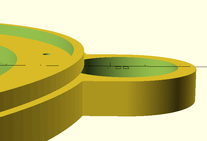
To drive the telescope left and right, I mounted it to a large base plate that slides on top of the 120-tooth spur. To facilitate the sliding action, I extruded a ridge from the base plate that slides in an accompanying ledge on the spur gear

ledge.PNG
ridge.PNG

This design is simple to print, but it can be be tough to get the tolerances right. Also, the plastic-on-plastic interface is not as good as a bearing. But with such a large circumference to cover, really the only way to make this smoother is to make a channel for individual ball bearings between the two pieces. Given that the only thing holding the pieces together right now is gravity, I wanted to avoid that. But it could be an improvement in the future.

A close up on the azimuth gear assembly

A close up on the azimuth gear assembly

The bevel gear-to-spur gear coupling does use a bearing, supported by the extra "loop" pictured above on the base plate. The small bevel gear is press-fit onto the motor shaft. Currently the press-fit bevel is a weak point in the design, as it occasionally slides loose. A future revision of the gear could include a collar that prevents it from sliding too far back.

Zenith drive

The challenge with zenith (up and down) is that the telescope body can't clip the base, despite needing to rotate a full 90º. One option is to rotate the telescope body around one end, therefore always keeping it away from the base. This causes the center of gravity to shift, however, and I'm not able to print a base large or heavy enough to handle that well. Luckily, my telescope is short enough that I can choose option 2: rotate around the center of gravity. This keeps the weight of the telescope body centered in the same place, but requires the support arms to be taller to keep the telescope away from the base.

A closer view of the support arms

A closer view of the support arms

You may notice the 10-tooth spur gear above. Here is how the drive motor mounts on the other side:

zenith_bevels.JPG

No reason not to reuse models here!

The telescope body is a cylinder, and I don't want to drill into it. So to mount it, I took some cues from its stock mount and used a pair of round bands that I could clamp together around the body. This band had to securely connect to the 120-tooth spur, so I ended up with the piece below:

zenith_mount.JPG

The band prints with two round pegs that fit into the bearings on the arms. To connect the spur to the band, I elongated one of the pegs so it can fit through the spur and the bearing. I then drove a screw through both pieces perpendicular to the axis to keep them together. I added a second screw through the face of the spur into the flat of the band for extra strength, but it may not be needed.

The bearings are super-glued into the arms. The pegs can be inserted into the bearings by bending the arms apart. Once inserted, the arms snap back together with enough strength to make a snug fit.

The entire gear assembly for zenith motion

The entire gear assembly for zenith motion

Electronics Mount

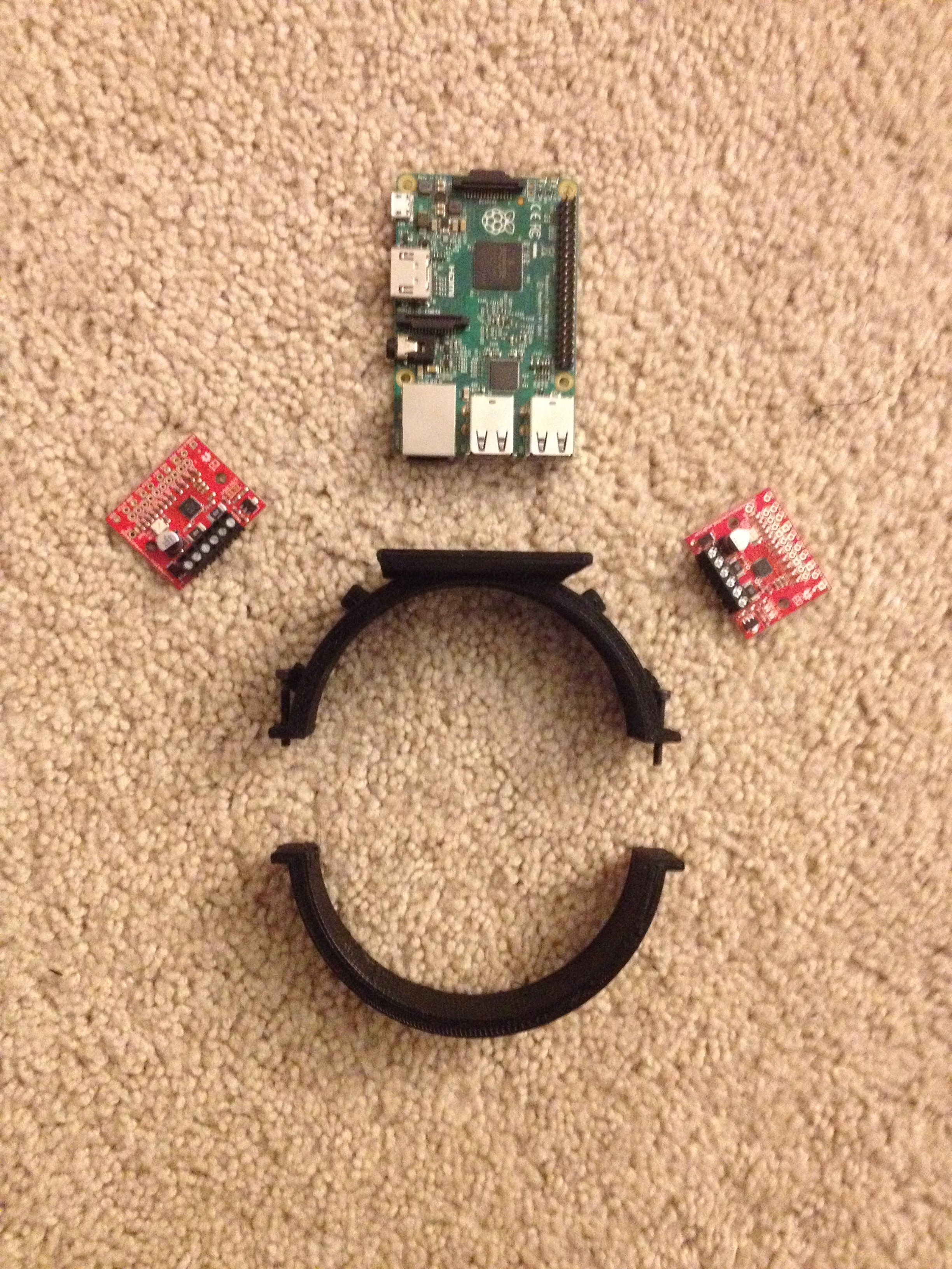
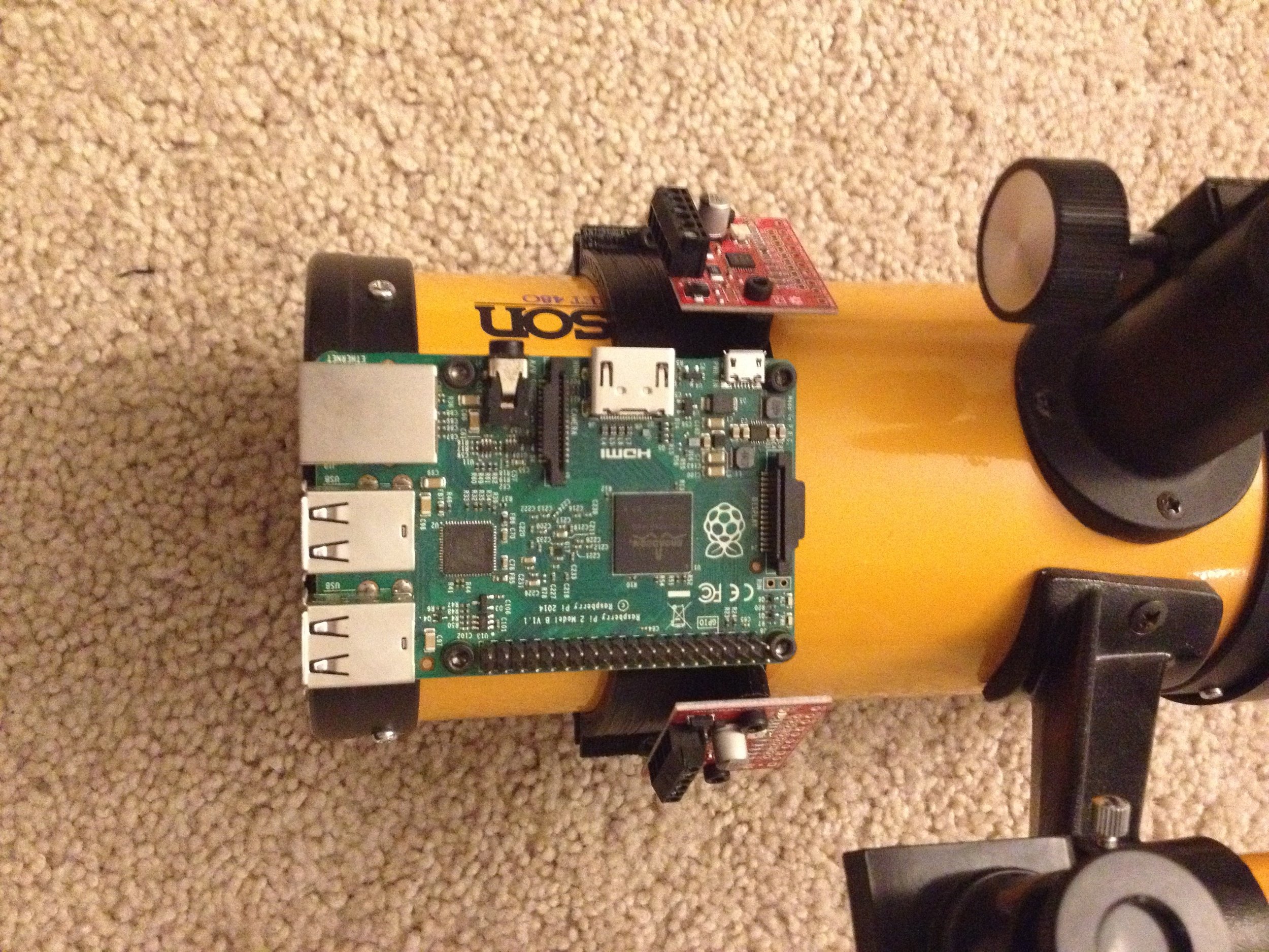
I'll just get this out in the open now: I'm using a raspberry pi for this project. I will get into all of that in the next post. Until then, here's how I mounted it:

electronics_ band.JPG
electronics_band_assembled.JPG

Another band of course! this method works pretty well, and doesn't damage the telescope at all. This band has been customized for the electronics pictured above, but it's easy to modify if I want to bolt on additional modules.

Full_Assembly.JPG

And here is the full mechanical assembly, realized in the flesh!

You can find the OpenSCAD files here.

In Sundry

Telescope Robotics Conversion Part 1: Intro

May 16, 2018 Spencer Allen
old_assembled.JPG

A long time ago I inherited the Jason Comet 480 pictured above. It's a small newtonian telescope that came with a tripod and a variety of filters. It was good for looking at the moon and some planets, but beyond that I never got much use out of it. It mostly sat in a closet until the fateful day that I got my 3d printer.

athena.JPG

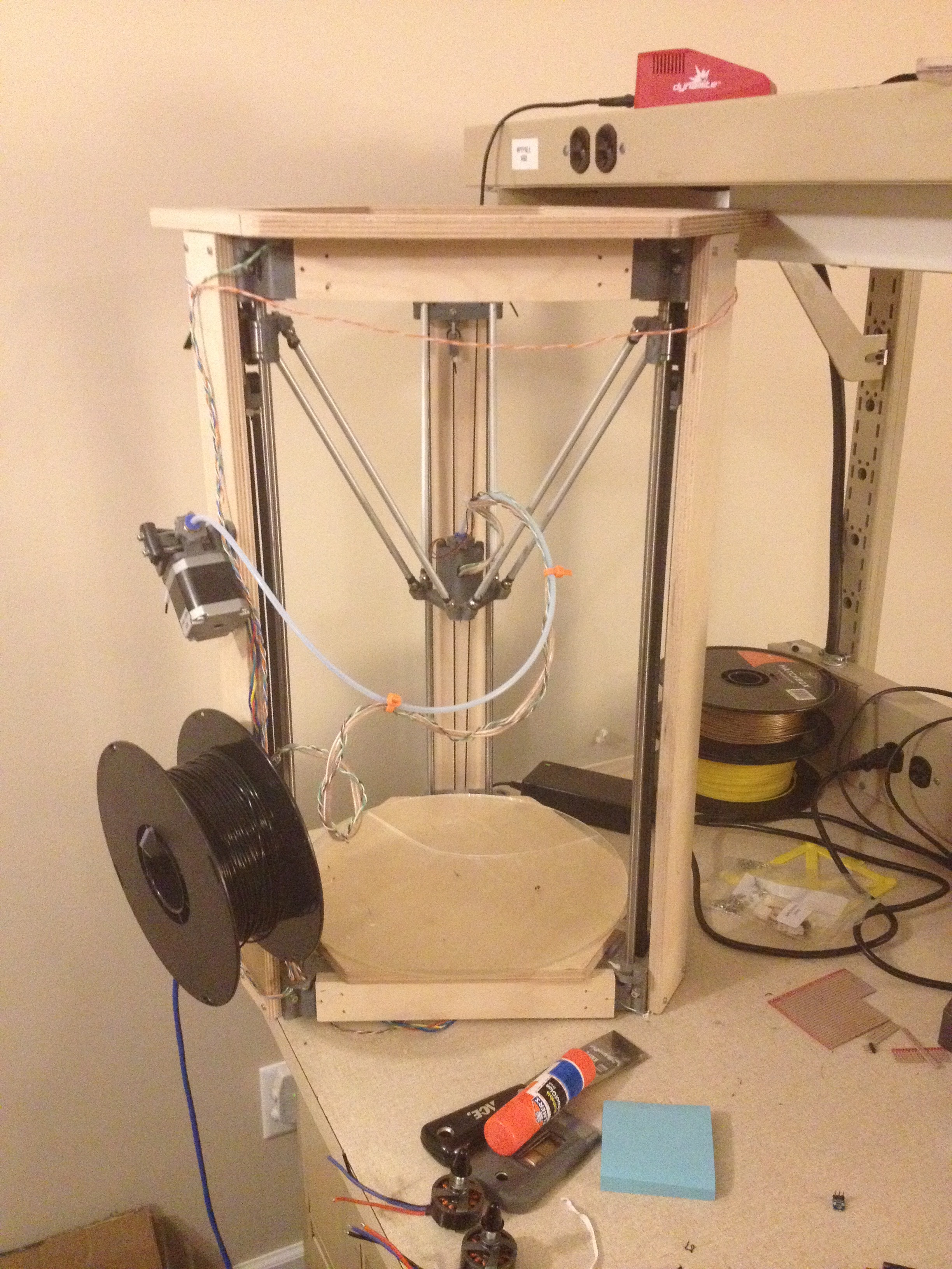
It's a delta printer called Athena (and it's open source!). Designed by the Michigan Tech open-source hardware group, I received the printer as part of EE4777. In that class, you were graded based off of a few build projects (that were hopefully mostly 3d printed). For the final project, we just had to build something "useful". While hunting around for project ideas, I came across that old telescope. I thought, wouldn't it be nice if I could breathe some new life into it?

My goal: design a robotics conversion kit for telescopes

With my Jason 480 as the guinea pig, I hoped to put together some 3d printed parts, stepper motors, and some kind of processor to allow the telescope to track objects in the sky. As a measure of success, I picked an object to attempt to track.

My target object: The International Space Station

The ISS is close enough and bright enough my Comet 480 should be able to see it. It's also fast enough that I shouldn't have to wait too long for it to transit within my veiwable sky. In fact, it's so fast it's impossible to get a good picture of without a tracking apparatus! That makes it a perfect target for us. If we can get a good image of the station, then we have a pretty good tracker.

My first attempt:

Went badly. I tried a design that was pretty shaky (literally and figuratively), and a long and important print failed the night before the showing. That is on top of completely overestimating the amount of time the electronics would take. Thankfully I had enough to show that I passed, but I basically threw out the whole project afterwards.

My second attempt:

After a year, a graduation, and a new job, I was looking for a project. I happened upon the old design files in my archive and decided to take another crack at it.

So far it's going well enough I thought I would write about it here. The next couple posts in this series will detail my progress so far.

In Sundry
  • Battlebots
    • Jul 22, 2023 Magnetometers: Software Implementation
    • Apr 21, 2023 Magnetometers: a Possible Way Forward
    • Apr 20, 2023 A Magnetometer Collides with Reality
    • Sep 20, 2022 A Rotating Coil Magnetometer for Meltybrains
    • Jan 9, 2022 Event Report: Robot Ruckus 2021
    • Dec 11, 2019 Event Report: Bugglebots 2019
    • Nov 15, 2019 Event Report: Robot Ruckus 2019
    • Nov 3, 2019 Hit N Spin
    • Jun 2, 2019 Halo Pt. 12: Gen 2 Electronics
    • Apr 20, 2019 DShot ESC's for Meltybrains
    • Mar 31, 2019 Halo Pt. 11: Mechanics of a Good Impactor [Guest Starring]
    • Nov 17, 2018 Halo Pt. 10: After Event Report
    • Aug 12, 2018 Halo Pt. 9: Accelerometer Calibration
    • Jul 1, 2018 Halo Pt. 8: Improved Accelerometer Algorithm
    • Jun 9, 2018 Halo Pt. 7: Improved Beacon Algorithm
    • May 23, 2018 Halo Pt. 6: The Code
    • May 23, 2018 Halo Pt. 5: Writing Reliable Code
    • Apr 30, 2018 Halo Pt. 4: The Electronics
    • Apr 29, 2018 Halo Pt. 3: The Big Idea
    • Apr 29, 2018 Halo Pt.2: Meltybrain
    • Apr 28, 2018 Halo Pt.1: A first adventure in combat robotics (Overview)
  • Meltybrain
    • Jan 9, 2022 Event Report: Robot Ruckus 2021
  • CuDL
    • May 10, 2020 The Formal Language Specification of CuDL
    • May 8, 2020 Introduction to CuDL
  • Sundry
    • May 19, 2018 Giant Audio Equalizer
    • May 18, 2018 Telescope Robotics Conversion Part 2: The Mechanics
    • May 16, 2018 Telescope Robotics Conversion Part 1: Intro

Powered by Squarespace